Well
Modeling of production and injection wells, with hydraulic, thermal and electrical calculations that account for downhole and surface equipment

Well modeling
in the browser
Model wells, analyze operating conditions and perform equipment calculations in a shared, browser-based workspace with centralized access management
Comparable engineering software
- 01PROSPERPetroleum Experts
- 02PIPESIMSLB
- 03WellFloWeatherford
Physics behind the model
PVT
Black-oil models and compositional equations of state (Peng–Robinson / SRK). Two- and three-phase equilibrium
Hydraulic calculations
Single-phase flow
Frictional pressure loss from the Darcy–Weisbach equation. Friction factor λ(Re, ε/D)
Includes pressure changes due to gravity and acceleration
Multiphase flow
- Beggs–Brill
- Hagedorn–Brown
- Orkiszewski
- Gray
- Duns–Ros
- Mukherjee–Brill
4 mechanistic flow models developed by BASIS
Thermal modeling methods
Full energy balance
Energy balance including enthalpy, heat transfer, kinetic and potential energy. Pressure effects, including the Joule–Thomson effect, are captured through enthalpy at local P and T
Enhanced approximation
Approximate energy balance using heat capacity and the Joule–Thomson coefficient. Includes heat transfer and elevation changes; neglects changes in kinetic energy
Simplified approximation
Temperature calculated from heat transfer to or from the surroundings, assuming constant heat capacities for each phase. Neglects the Joule–Thomson effect and changes in kinetic and potential energy
Browser access with centralized updates, without a full desktop client
Collaboration with project-level access control
Change history and saved model states
Ready-to-use vendor catalogs, with tools to define equipment and build custom catalogs
Configurable units of measurement and light and dark themes
User guides, technical guidance and interactive courses within the platform
Well operating methods
and configurations
Build a model that reflects your well configuration and operating method, including natural flow, dual-zone production and multilateral wells
Production wells
Steady-state modeling and operating-point determination from inflow and vertical lift performance curves
Injection wells
Hydraulic and thermal calculations for water and gas injection, accounting for well configuration and the properties of the injected fluid
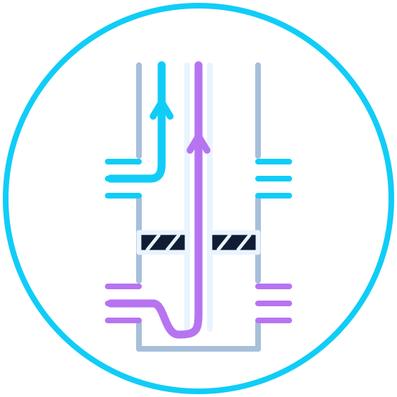
Dual-zone production
Two zones isolated by a packer, producing separately through the tubing and annulus

Multilateral wells
Multilateral wells with lateral branches for production and injection
Product interface
Well builder
2D well model with an ESP, component properties and input validation
Coupled modeling
for ESP and ESPCP wells
Hydraulic, electrical and thermal calculations are coupled. Heat from the motor changes fluid temperature, which feeds back into the hydraulic calculation
Hydraulic calculations
The pressure profile, operating flow rate and pump head–flow curve determine the required pump power
To electrical calculations: pump powerElectrical calculations
Motor load, current, efficiency, electrical power consumption and equipment losses
To thermal calculations: motor heat lossesThermal calculations
Wellbore heat transfer and heat from the motor determine the fluid temperature
Back to hydraulic calculations: updated temperatureFluid properties are updated in the hydraulic and thermal calculations to produce consistent profiles and equipment parameters
Profiles and model calibration
Pressure and temperature along the entire well. Automatic coefficient calibration with full profile recalculation and deviation monitoring
Liquid unloading in gas wells
Compare actual and critical velocities along the well to assess upward gas-liquid flow
Pressure gradients and losses
Phase velocities and liquid holdup
Flow regime and phase flow rates
Fluid PVT properties
Nodal analysis
Determine the operating point from IPR/VLP curves, compare operating scenarios and generate vertical flow performance (VFP) tables